


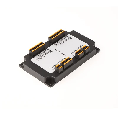


3 Phase Driver
Model:MDSM90B96G-2


Overview
1. Three phase output drive
Each channel adopts three-phase inverter output, combined with vector control to achieve closed-loop regulation of motor current and voltage. The current is continuously controllable, the torque output is smooth, the motor response is fast, and the backlash is small. For AGV's precise parking, constant speed cruising, and low-speed climbing conditions, this control method is more relaxed than simple on-off commutation.
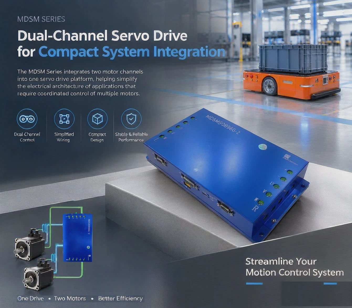
2. Compact integrated structure
AGVs commonly use integrated chassis, and the cabin space is tight. This model integrates dual channels into a 270 × 150 × 48 mm, approximately 1.9 kg body, and only requires one installation position for the two motor drives. During installation, an aluminum radiator should be added to the bottom and ensure good ventilation (protection level IP32) to avoid excessive temperature rise during long-term full load.
3. Control mode and parameter tuning
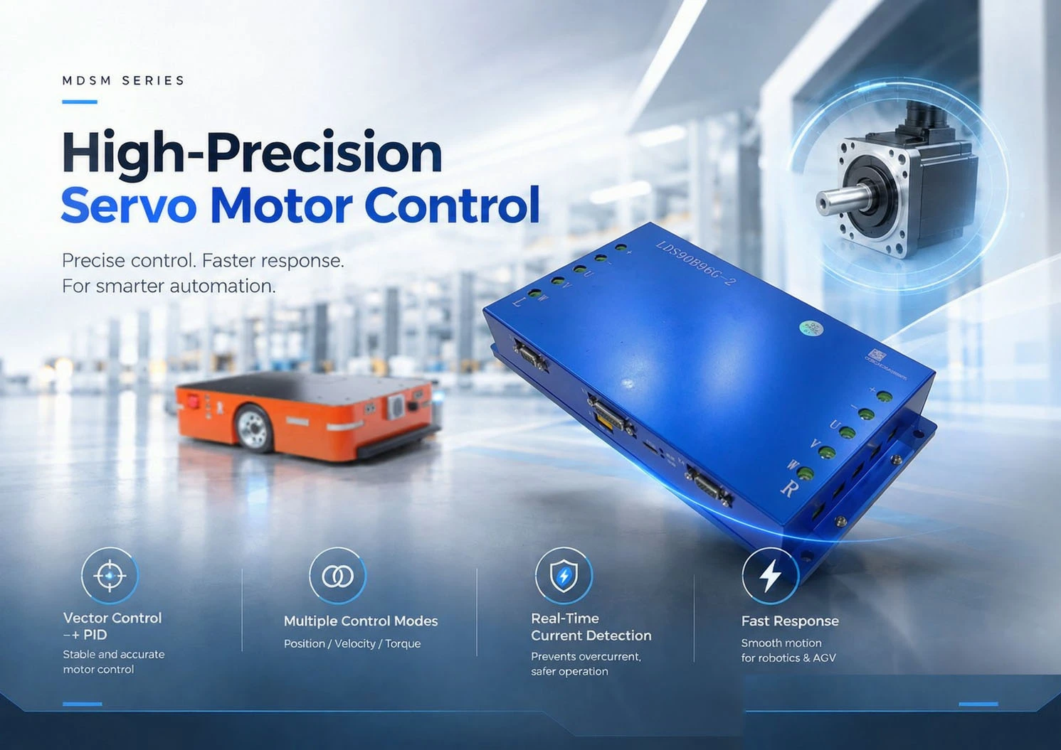
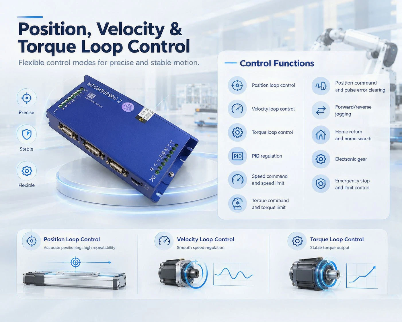
Built in vector control and PID regulation algorithm, factory default is speed loop; Supports three types of closed-loop systems: position loop, speed loop, and torque loop. It can switch operating modes, speed loop gains, and set torque and speed limits through communication or digital input. The operating parameters are issued and saved by the upper computer debugging software, and the setting values can be reused according to the vehicle model - this is not the same as "automatic adjustment according to the environment", and the actual performance depends on the parameter table set by the debugging personnel.
4. Instruction reception
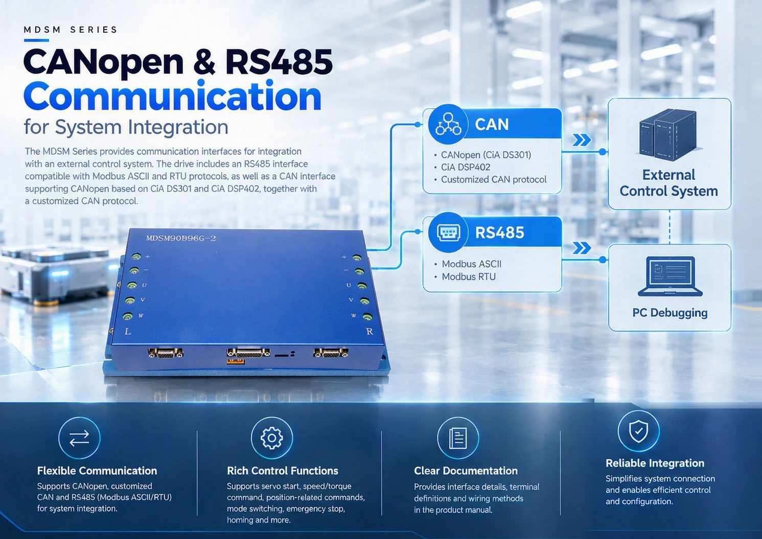
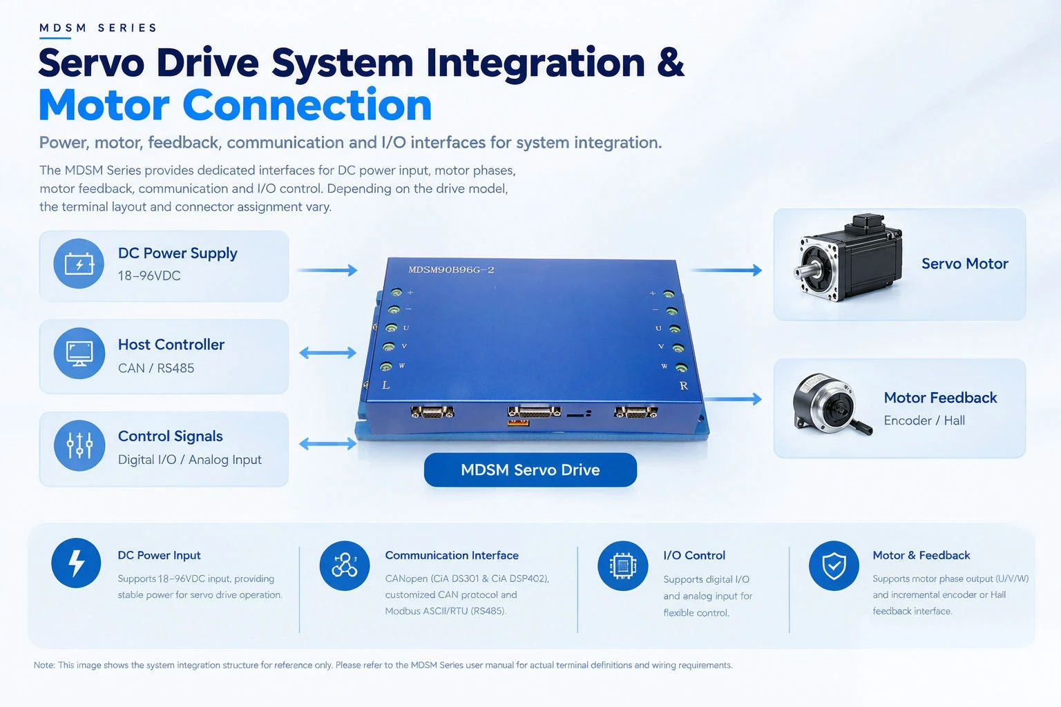
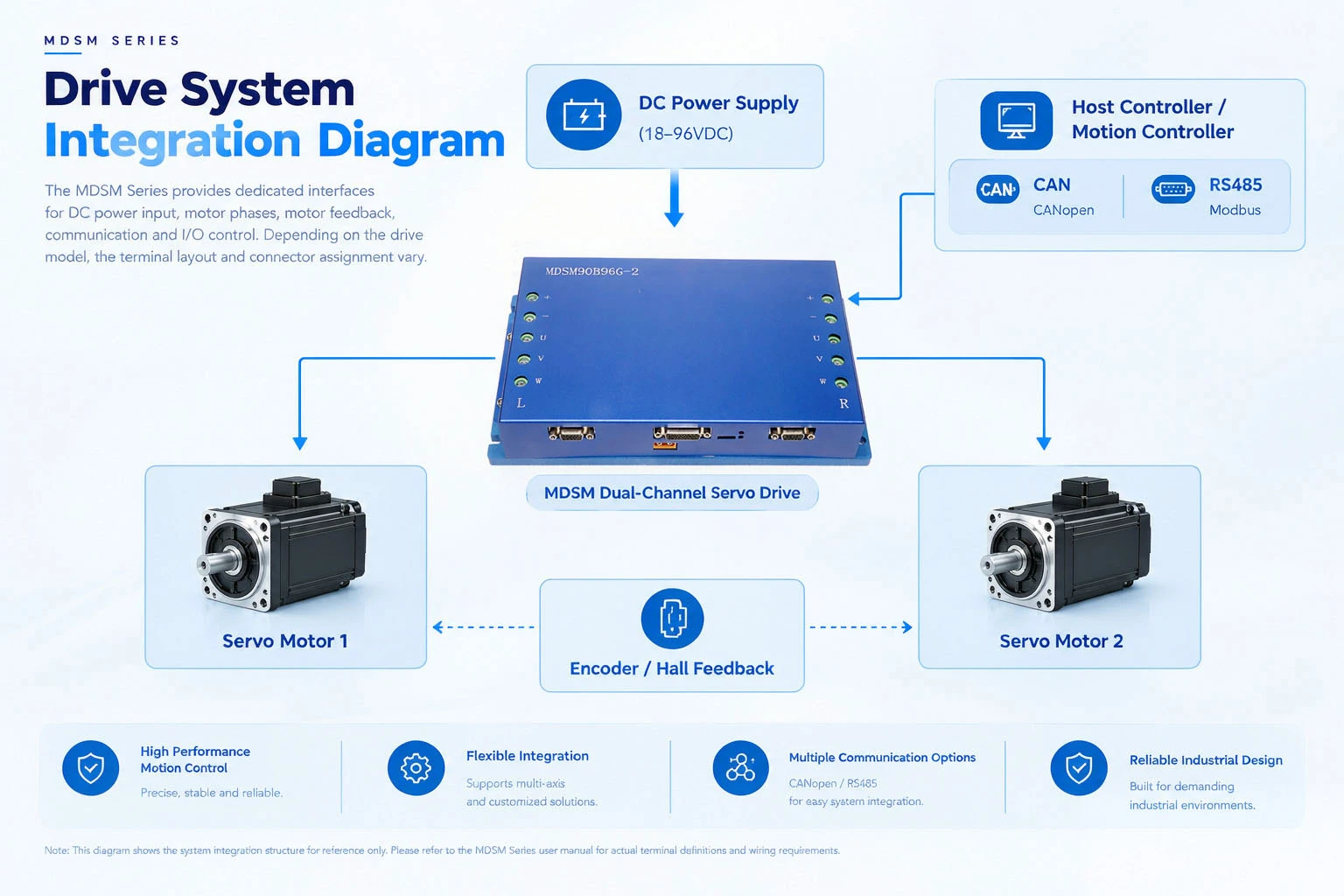
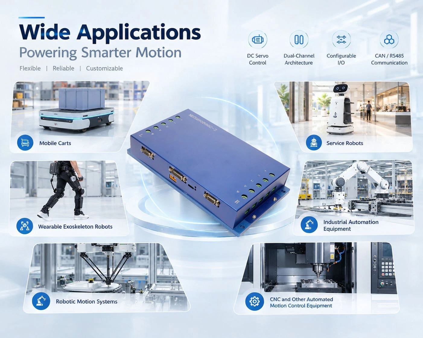
The motion command is controlled by the AGV master via CAN (CANopen CiA DS301/DS5402 or custom protocol) RS485(Modbus ASCII/RTU), Issued through 2 channels of 0-5V analog input or 7 channels of digital input (3-12 VDC), covering servo enable, target speed, torque limit, position command trigger, emergency stop, forward and reverse limit, zero return and abnormal reset, etc. The acceleration and deceleration curves are generally planned by the vehicle controller and executed by the driver according to instructions.
5. Power conversion link
AGV is powered by batteries, and the input of this model is 18-96 VDC DC. There is no rectification link inside: the DC bus is stabilized and stored in a capacitor bank, and the motor is driven by three-phase current output from a three-phase inverter bridge. The feedback energy generated by braking or deceleration can be dissipated through an external discharge resistor connected to the discharge interface (recommended in the manual as 20 Ω/500 W or 1 Ω/1000 W) to avoid triggering overvoltage protection due to bus voltage rise.
6. Motor control and feedback
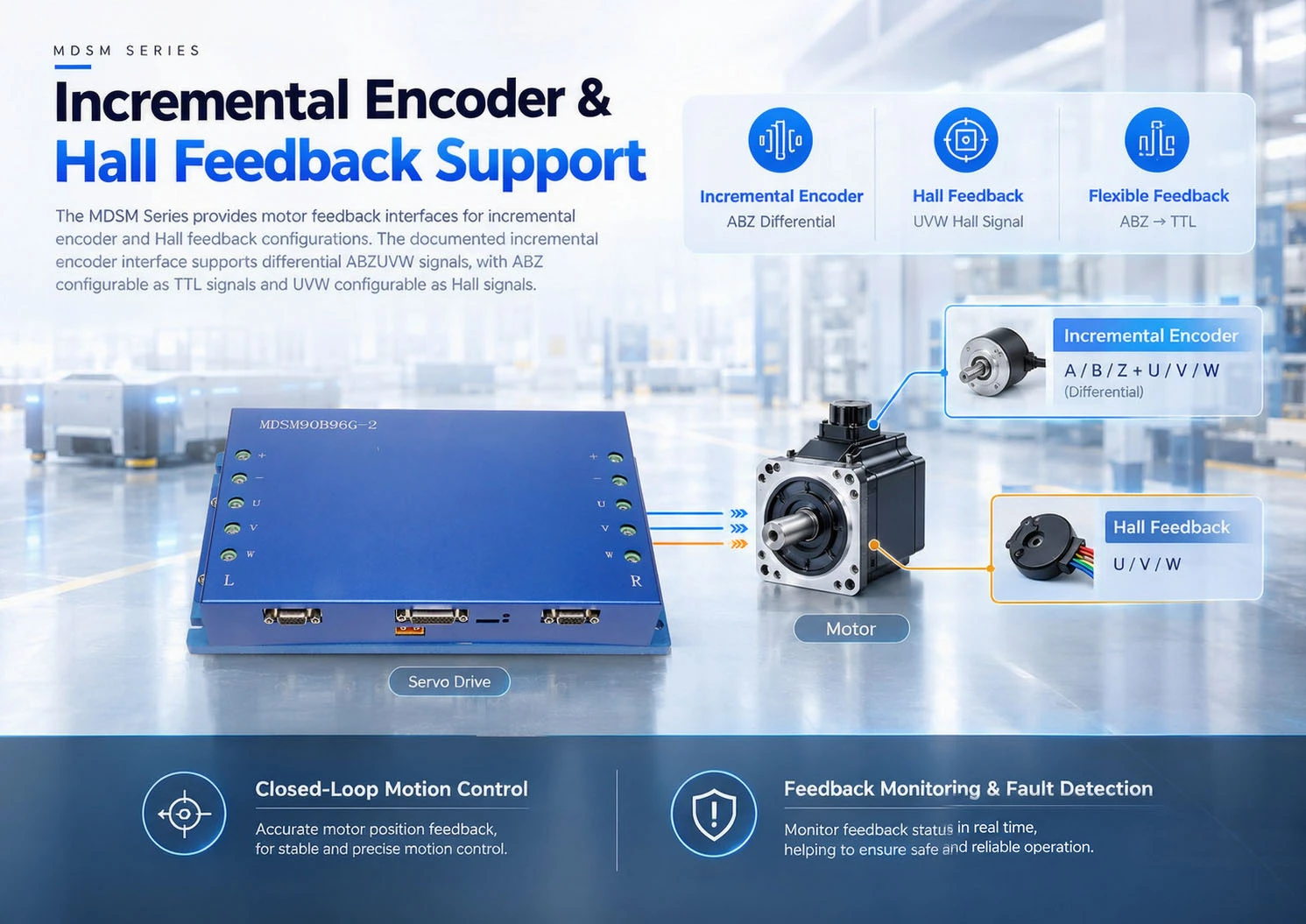
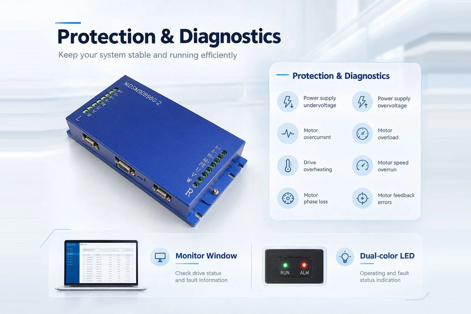
The driver performs closed-loop control on current and voltage to accurately control speed, torque, and steering; Real time acquisition of position and velocity through ABZUVW differential incremental encoder, with ABZ configurable as TTL and UVW configurable as Hall. Under closed-loop conditions, the motor travels at a predetermined trajectory and speed. 90 A continuous, 180 A peak, 6 s overload capacity (recovery takes about 90 s, requires external heat dissipation), can cover heavy-duty starting and short-term climbing.
features




Products details

Dimension

Specification
|
ltem |
Parameters |
|
Model |
MDSM90B60G-2 |
|
Limit Power Supply Range |
18~96VDC |
|
Single Channel Rated Current |
90Arms±2% |
|
Single Channel Maximum Current |
180Arms±1% |
|
Maximum Overload Time of Single Channel |
6S |
|
Single Channel Overload Recovery Time |
90S |
|
Rated insulation withstand voltage |
Input and output DC 1000V leakage current to the enclosure less than 3mA. |
|
Drive Frequency |
6~16KHz±0.1KHz |
|
Insulation resistance of the whole machine |
≥1M at 40°temperature and 95%humidity |
|
Power Control Method |
Vector control |
|
Mean time between failures(MTBF) |
≥5000 hours |
FAQ
01.Is 90 A for each channel or for the whole machine? How long can the peak of 180 A last?
02.What are the advantages of dual channel versus buying two single channel drivers?
03.Where should I check first if the CAN connection is not working or if there is occasional packet loss?
04.Why does the motor report power overvoltage when it suddenly stops or loses power? Do discharge resistors need to be connected?
05. What is the reason for the alarm not being cleared or immediately reporting again after clearing?
06.This model does not have a pulse+direction interface. How to issue commands in position mode?


Hot Tags: 3 phase driver, China 3 phase driver manufacturers, suppliers, factory, servo motor driver for intuitive interface, servo motor driver for precise positioning, analog servo motor driver, servo motor driver for smooth operation, servo motor driver for rectifiers, servo motor driver for spare part


